En (UK)
  De
De zh-CN
zh-CN Se
Se En (US)
 Nl
Nl Fr
Fr
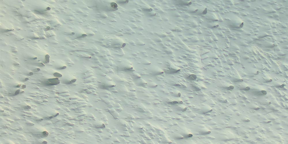
Table of content
How to prevent comet tails in semi-automatic metallographic sample preparation
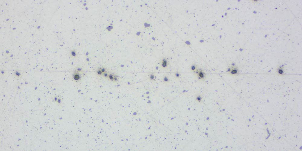
In metallography, a comet tail is a preparation error that occurs when samples are clamped in a holder during grinding and polishing, resulting from a hard particle or a hole in the material interacting poorly with the polishing cloth.
To stop comet tails from appearing, a structured approach must be used. Carefully control the grinding and polishing steps to ensure the material is removed evenly.
Why comet tails are a problem
These errors are a problem because they change the true shape of the metal features.
Inclusions and pores look larger or longer than their real size. This leads to incorrect data in inclusion ratings. It also hides the boundary between the particle and the metal, which makes it impossible to see the true microstructure.
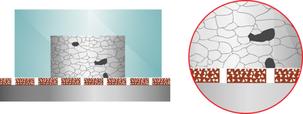
It is important to note that comet tails are often caused after the creation of relief. Relief is a height difference that occurs because the soft metal has a higher removal rate than the hard particles. This creates a small height difference. This height difference causes the polishing cloth to flow unevenly, which creates the tail. That means if there is no relief, no comet tail is created.
Consequences of Comet Tails
- Wrong measurement of inclusion content: The tails hide the real edges of the inclusion. This makes inclusions look larger than their true size.
- Difficult to do material analysis: It is hard to see the different phases of the metal clearly or identify the material composition.
- Problems with Automatic Image Analysis Software: The software cannot see the difference between a real inclusion and a comet tail. It counts them as one single, long object. This results in a “fail” for cleanliness standards, even if the metal is of a high quality.
Topics in This Guide
- Definition of the comet tail effect.
- How to identify comet tails.
- Step-by-step guide to remove comet tails.
- Final thoughts: Comet Tail Prevention
How to Identify a Comet Tail in Metallography?
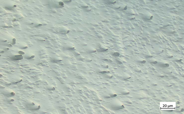
A comet tail has a “head” and a “tail”:
- The “head”: This is a hard inclusion (like an oxide or carbide) or a pore/void trapped in the matrix.
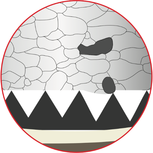
- The “tail”: This is a shallow, elongated groove in the surrounding matrix. It looks like a blurred streak trailing away from the “head”. The tail forms when the polishing cloth and abrasives move in a single direction for too long. The hard particle blocks the flow of the abrasives, forcing them to erode a groove into the soft metal behind it.
In semi-automatic or automatic systems, the polishing dynamics (how the material removal rate is proportional to the applied force and the relative velocity between the sample and the polishing cloth) are the parameters you change to achieve a repeatable, high-quality surface. To optimise your results, it is important to understand how these parameters affect the process. Here are the primary factors that lead to the formation of comet tails:
- Speed: It is caused by the relationship between the speeds of the disc and the sample holder. For example, at a disc speed of 150 rpm, different holder speeds create different velocity vectors (a combination of speed and direction of movement), see figure 1.
- Hard particles (non-metallic inclusions) change the path: Because the inclusions are hard, they stop the abrasive from moving in a straight line. The abrasive is forced to move around the particle, which cuts a deep groove into the soft metal directly behind the particle.
- Uneven Removal: The abrasives cut the soft metal much faster on one side of the inclusion than the other. This creates an uneven surface.
This creates a long trail. These trails are a problem because they change the real size and shape of the inclusions.
How to Identify and Assess Comet Tails
Before you make changes, you must identify the preparation fault correctly. Comet tails can look like other defects, such as scratches, pull-outs (holes where particles were torn out), or embedded abrasives (particles stuck in the surface). To confirm it is a comet tail, look for these signs:
- Appearance and direction: They look like long trails that always follow the direction of the polishing motion.
- Location: They only appear around hard phases or empty spaces (voids) inside a softer metal.
- Development: The effect gets worse during the final polishing steps because often softer cloths are used; the soft matrix wears down much faster than the hard inclusions.
- The importance of cleaning: You must clean the sample thoroughly between every step to avoid contamination. If a groove forms, it can trap tiny pieces of diamond or debris. If this debris moves to the next step, it will cause deep scratches.
Step-by-Step Guide to Eliminating Comet Tails
Step 1: Control the Machine Settings
This defect depends on the speed of the holder and the disc. We must look at the velocity vectors, which is the relative speed and direction between the holder and the surface, see figure 1. Assume the disc speed is 150 rpm.
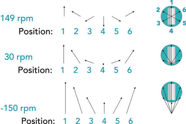
- Similar speeds (synchronous = same speed): For example, 150 rpm for the disc and 149 rpm for the holder (in modern machines, if one sets the rotational speeds to 150/150 rpm, there usually is a difference of a few rpm between them). In co-rotation, the disc and holder rotate in the same direction at similar speeds. This causes the direction of the relative speed to turn constantly. This means the abrasive engages the inclusion from every angle, preventing a tail from forming, giving an even scratch pattern, that is to say uniform deformation.
- Large speed difference: When the speed of the sample holder is much slower than the speed of the disc 30/150 rpm, the structure is likely to develop comet tails. Soft cloths are flexible and will not keep samples flat. Together with directional polishing that will result in comet tails. The abrasives travel in the same path over and over. This constant flow from one direction wears away the soft metal behind the inclusion, creating a long, straight comet tail. Also shown on figure 4.
- Counter-rotation (e.g., setting the grinding disc to 150 rpm and the specimen holder to -150 rpm) significantly increases the relative speed between the sample and the abrasive. Under these conditions, the abrasive particles impact the hard inclusions or secondary phases with substantial energy. This intense mechanical interaction results in the formation of deep, elongated comet tails.
- Machine setting recommendation to prevent comet tails: Use co-rotation with similar speeds. If the speed difference is more than 5–10% [1], the risk of comet tails increases.
Step 2: Improve the Grinding Process
Good polishing starts with correct grinding.
Select the Correct Grinding Discs for Plane and Fine Grinding
Plane grinding is the initial step used to remove all damage from cutting to make the surface plane. Both plane grinding and fine grinding are usually performed with rigid discs. Using rigid discs ensures that the samples remain flat. If the surface is not perfectly flat after grinding, polishing will not correct it. Instead, polishing will make the ‘height difference’ (relief) deeper and increase the risk of getting comet tails.
To prevent comet tails, select your grinding discs based on the material properties and the grinding step as outlined below:
- Plane grinding of materials harder than 150 HV: Use diamond grinding discs like Aka-Piatto and Aka -Piatto+.
- For fine grinding: Use rigid grinding discs like Aka-Allegran or Aka-Largan with diamond suspension to keep the samples flat.
- For soft materials: Use grinding paper (e.g. Akasel’s Rhaco Grit) but only for the plane grinding step.For fine grinding use a rigid grinding disc like Aka-Largan to ensure that the samples remain plane.
- Avoid paper: Do not use SiC or Al2O3 grinding paper for all grinding steps. Paper is flexible and creates relief, which leads to comet tails.
Step 4: Optimise the Final Polishing (Oxide Polishing)
This step is the most sensitive for comet tail formation because it is usually performed in counter rotation and it is a chemical mechanical removal.
When oxide suspension like Fumed or Colloidal Silica or Alumina are used, there are some recommendations for the preparation step in order to prevent comet tails:
- Short final step: Final polishing should be kept as short as possible. Over-polishing with oxide suspensions quickly creates relief, which might lead to comet tail formation.
- Clean the cloth and sample: In the last 10–20 seconds, flush the cloth with water while the machine is spinning. This removes the chemicals and prevents staining.
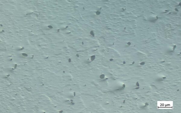
If you see a comet tail, do not just keep polishing. You must go back to a rigid grinding disc (Allegran or Largan) to flatten the surface (remove the relief) before attempting to polish again with the correct co-rotation settings.
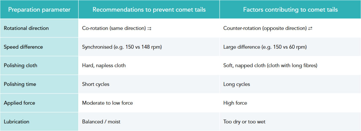
Quick Summary: How to Eliminate Comet Tails
Final Thoughts: Comet Tail Prevention
The comet tail effect is a notable challenge in metallographic sample preparation that can be avoided. By applying the correct polishing dynamics, ie. co-rotation, similar speed and appropriate force, while also selecting the right consumables, you can eliminate these artefacts. This allows you to achieve high-quality surfaces that are free from defects and no comet tails.
At Akasel, we specialise in high-performance metallographic solutions. These products are designed to help metallographers optimise their sample preparation process.
Vocabulary
- Artefact: A defect on a sample caused by the preparation process.
- Co-rotation: When the disc and holder turn in the same direction.
- Dosing: How much liquid (diamond/lubricant) you use.
- Inclusion: A small particle of a different material (often non-metallic) trapped inside a metal.
- DIC: Differential Interference Contrast – microscopy filter that enhances height differences.
- Matrix: The surrounding material that holds the inclusions or other phases.
- Napped cloth: A cloth with soft, long fibres.
- Phase: is a physically distinct, chemically homogeneous, and mechanically separable portion of a material’s microstructure.
- Relief: A surface condition where different parts of the sample have different heights because they have different removal rates.
- Unidirectional: Moving in only one direction.
- Velocity vector: A quantity that includes both the speed and the direction of movement.
Reference:
“Metallographic and Materialographic Specimen Preparation, Light Microscopy, Image Analysis and Hardness Testing” By Kay Geels, ASTM International, ISBN 978-0-8031-4265-7, 2006